Pacific Gyre Pressure Sensor
Overview
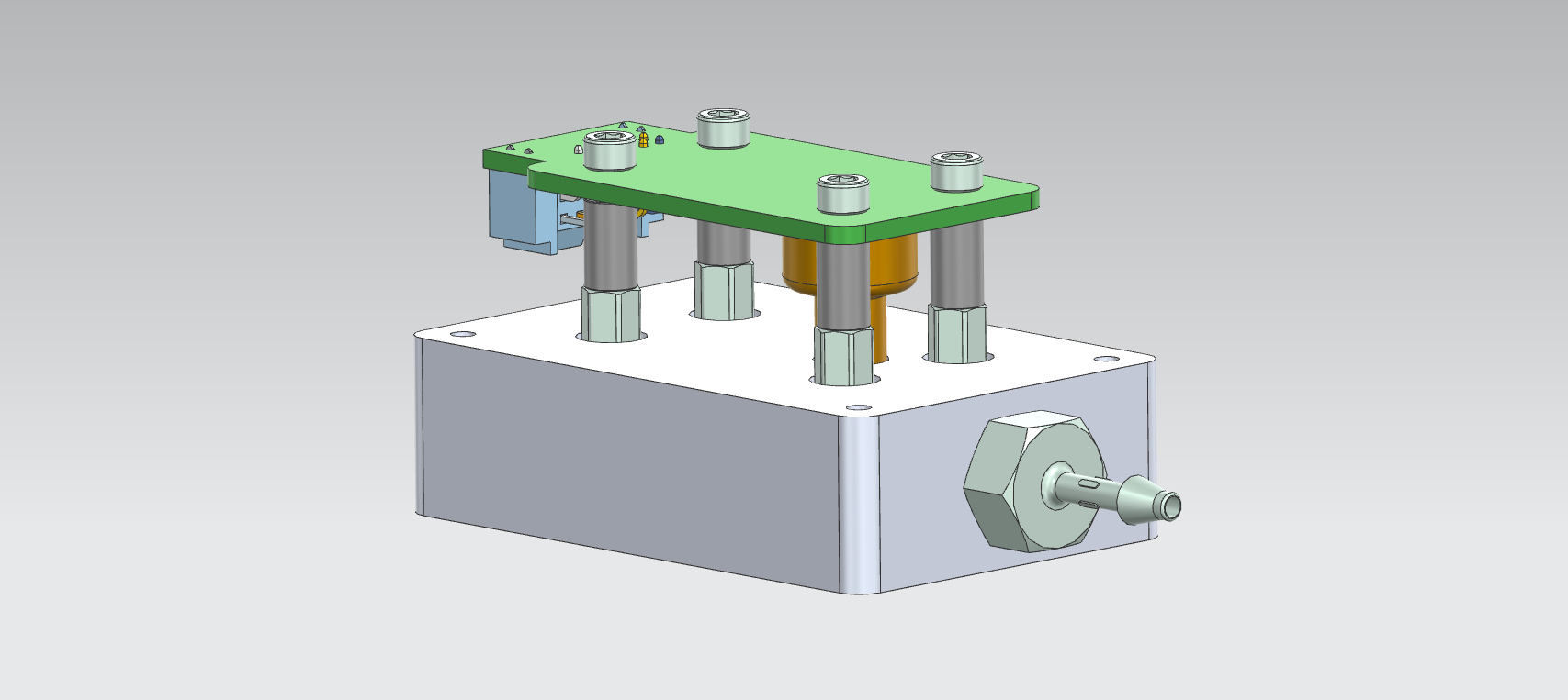
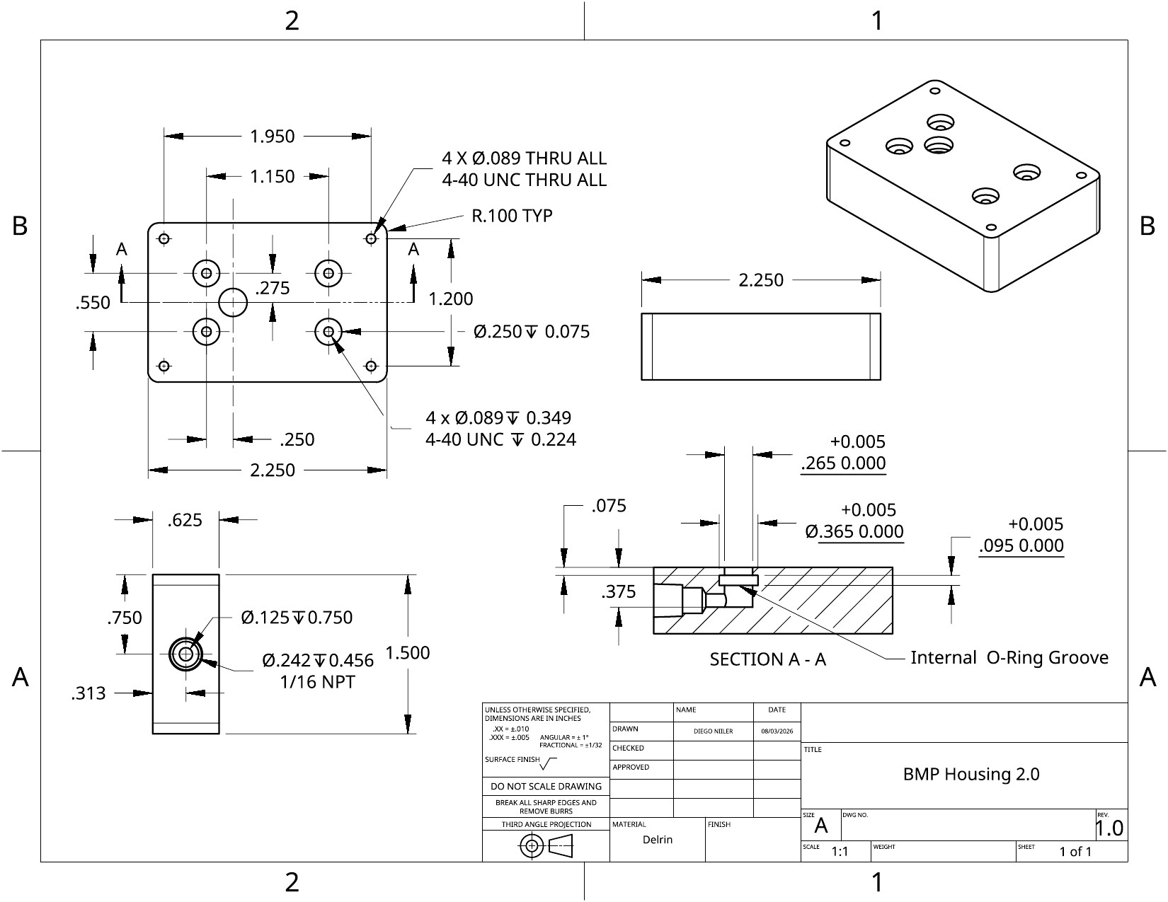
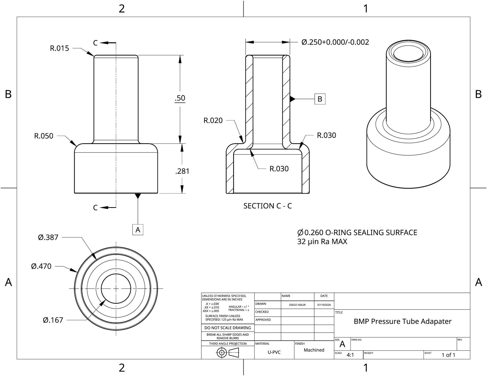
At Pacific Gyre, I worked across mechanical, electrical, and firmware boundaries rather than treating the sensor board as an isolated PCB. I designed the BMP sensor's low-profile mechanical housing in CAD, including its PCB mounting pattern, side pressure-fitting interface, internal O-ring groove, and fit beneath the existing water trap. I then integrated that housing with the PCB, pressure-tube adapter, standoffs, and connector-access requirements and developed an STM32U5 SPI readout path for pressure and temperature data.
Skills: Altium PCB · Assembly CAD · Embedded C
Goals
I needed to design a compact mechanical housing for the BMP sensor and integrate its PCB, seals, pressure fitting, and embedded readout as one verifiable system.
- The housing to remain below the existing water-trap height and fit the available drifter envelope.
- Locate the PCB on four repeatable mounting points while sealing the sensor cavity with an internal O-ring groove and side pressure fitting.
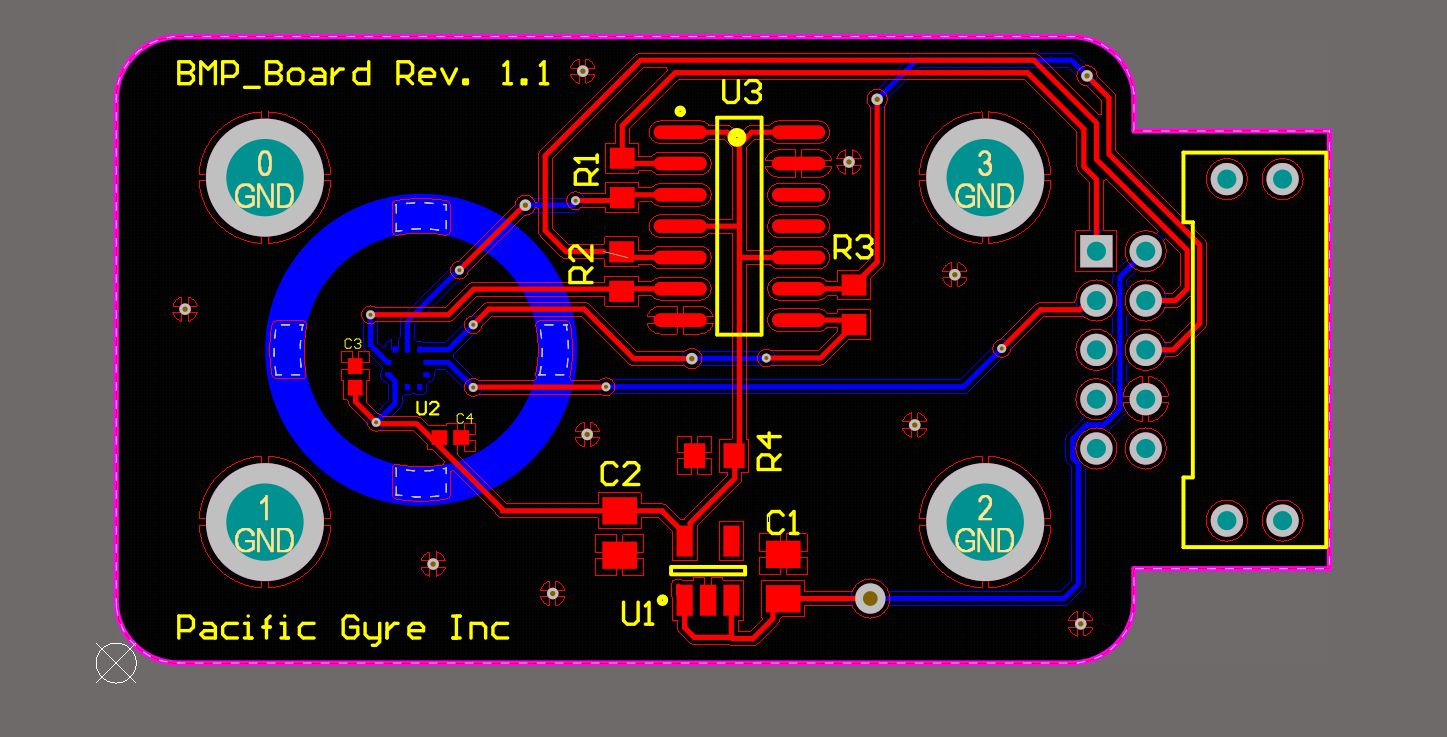
- Route the pressure-sensor PCB and clear the manufacturing design-rule checks.
- Read pressure and temperature over SPI with explicit error handling.
- Confirm the final sensor variant before full-system validation.
Design
Translated the drifter envelope, water-trap height, mounting pattern, pressure path, and sealing requirements into the housing geometry.
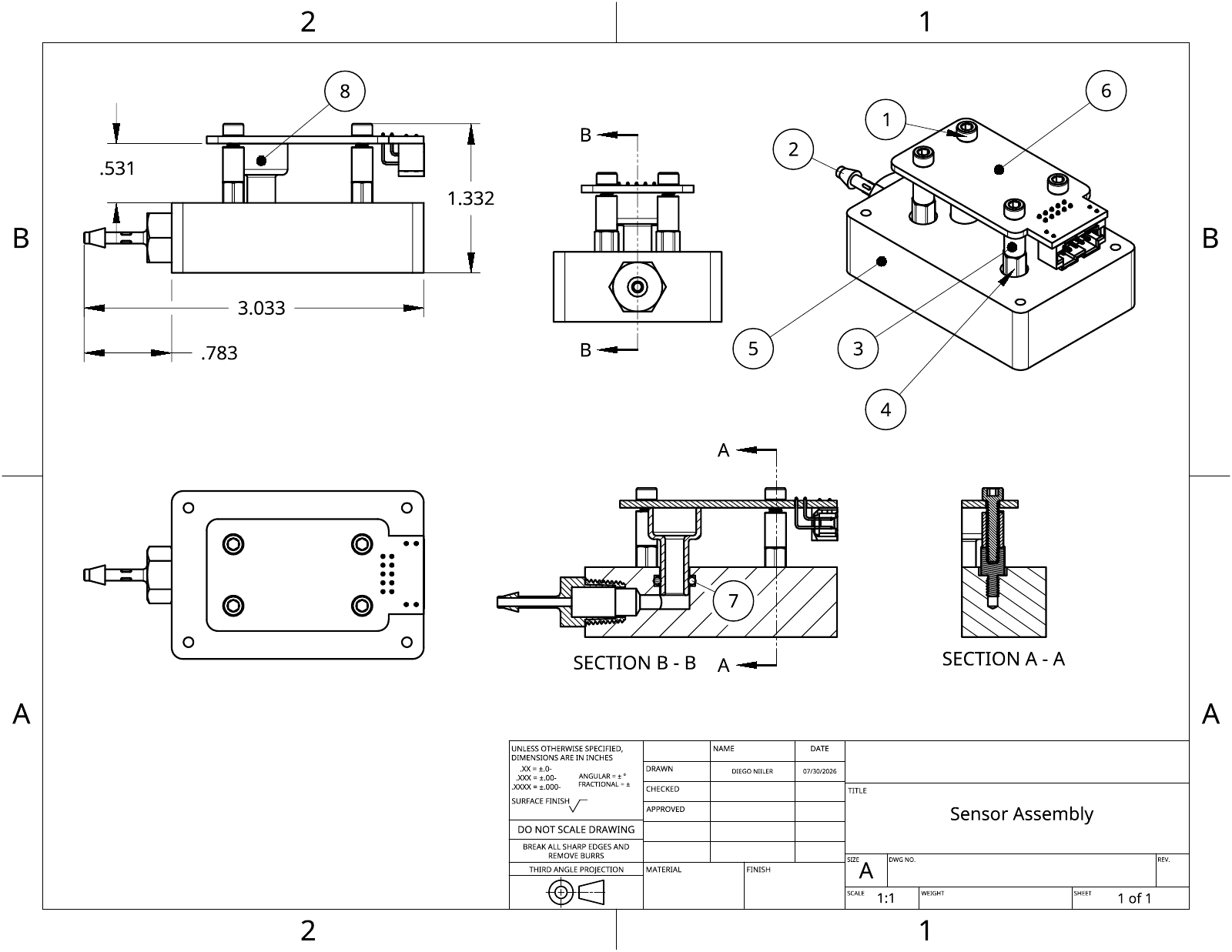
Modeled the low-profile housing, side fitting interface, internal O-ring groove, PCB standoffs, and pressure-tube adapter as one integrated CAD assembly.
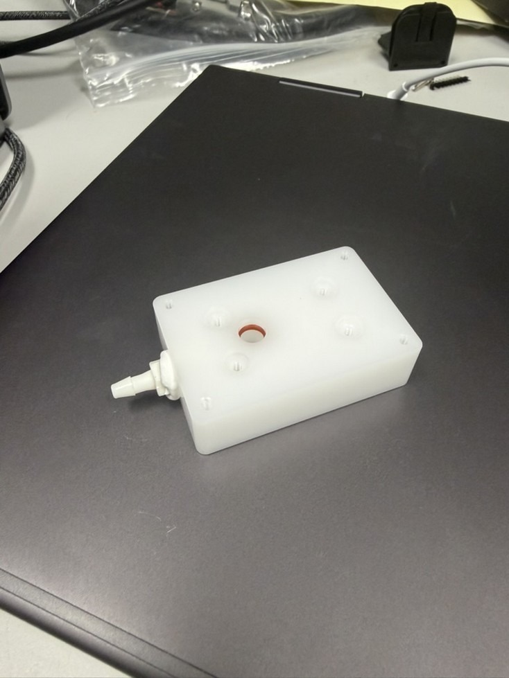
Produced the housing and assembly drawings and evaluated a printed prototype against the physical interfaces.
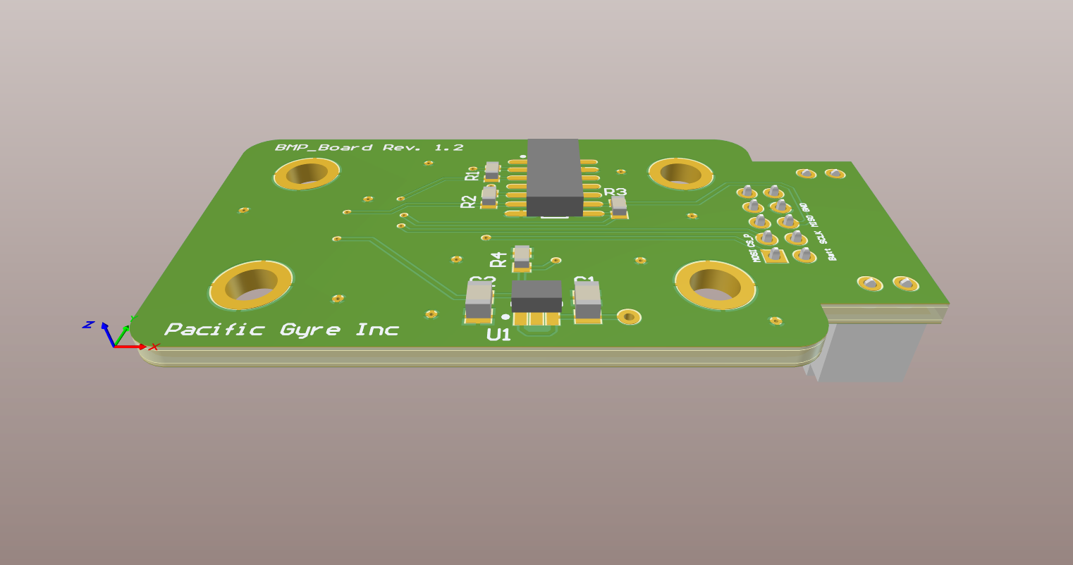
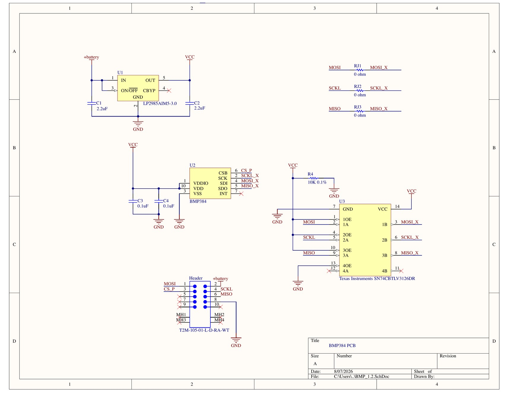
Routed and reviewed the PCB against the mechanical constraints and checked the board in 3D inside the assembly.
Implemented the STM32U5 SPI pressure and temperature readout with explicit failure handling.
Remaining validation sequence is to confirm the sensor revision, verify the assembled interface, and calibrate the completed device.
Outcomes
I completed the BMP housing CAD and drawing, a printed housing prototype, the integrated sensor assembly, and the documented PCB layout and 3D board review. The housing drawing defines the low-profile geometry, four-point PCB mounting pattern, side pneumatic fitting, and internal O-ring groove; the assembly drawing captures how the housing interfaces with the PCB, standoffs, and pressure-tube adapter. The June 30 Altium design-rule report recorded zero violations, and my STM32U5 source implements SPI pressure and temperature acquisition with explicit error handling. The files I have provided do not yet document calibrated accuracy or final board-to-firmware validation, so I do not present those as completed results.
- Cleared the archived PCB design-rule check with zero violations, which verifies the layout rules but not sensor performance.
- Identified a cross-disciplinary revision mismatch because the archived schematic and firmware name different sensor variants.
I learned that PCB placement, mounting hardware, connector access, sealing, and the pressure path must be reviewed together because a locally correct design can still fail at the system level. I also identified a revision-control issue: the archived schematic names a BMP384 while the firmware targets a BMP581. Before I call this a validated instrument, I need to confirm the final sensor variant, verify the assembled communication path, and collect calibration data over the intended pressure and temperature range.