Bicycle Brake Caliper
Overview
I worked with my team to take this brake from requirements through analysis, manufacturing, and physical validation. We first produced topology-optimized SLS arms with through-holes, but the printed geometry did not fit and adjust correctly on the bicycle. I helped document why that iteration failed, then used the installation findings and FEA results to support a simpler, stiffer redesign that could actually function as a braking system.
I owned the project documentation and connected the team's design decisions, FEA results, failed first prototype, redesign, installation, and physical braking test into the final engineering report. I also participated directly in the design and validation work.
Skills: NX CAD · FEA · SLS Nylon 12
Goals
My team and I needed to develop a lightweight brake caliper, learn from a failed topology-optimized prototype, and redesign it into a functional system that could pass both analytical and physical tests.
- Stop the bicycle within the 7.62 m ISO-adjusted threshold.
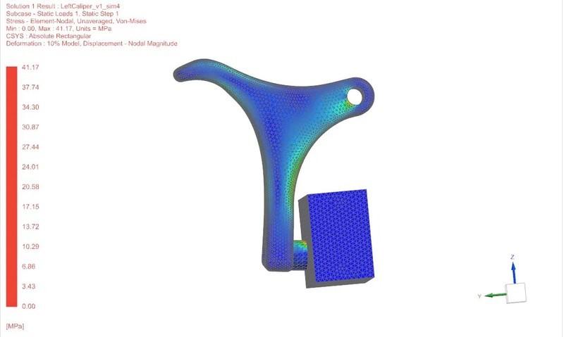
- Keep simulated peak stress below 50 MPa and total deflection below 11 mm.
- Maintain an actuation force below 180 N and a prototype mass below 150 g.
- The caliper to fit the bicycle interfaces, release the pads, and provide usable adjustment.
Design
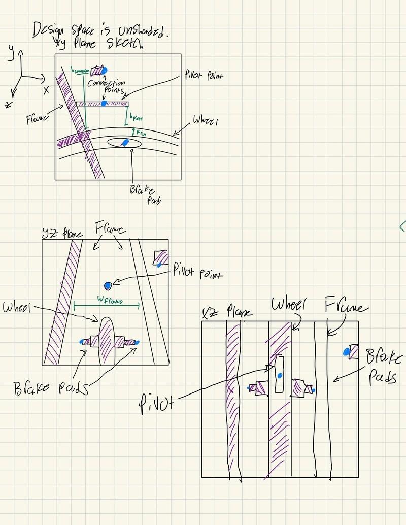
Helped translate the user needs into ISO-based stopping, force, mass, stress, and deflection targets.
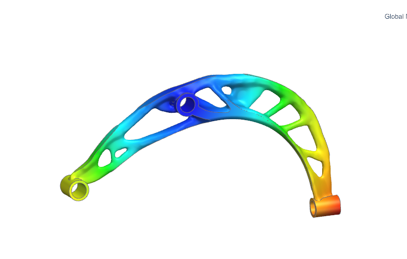
Developed the NX geometry, FEA models, and first topology-optimized arms through Week 7.
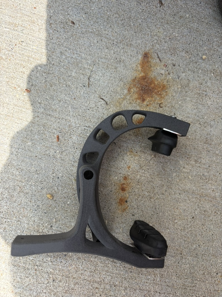
Installed the first SLS prototype in Week 8 and documented the through-hole geometry and interface problems that prevented it from working correctly.
Simplified the geometry, corrected the interfaces, and increased arm stiffness in the Week 9 redesign.
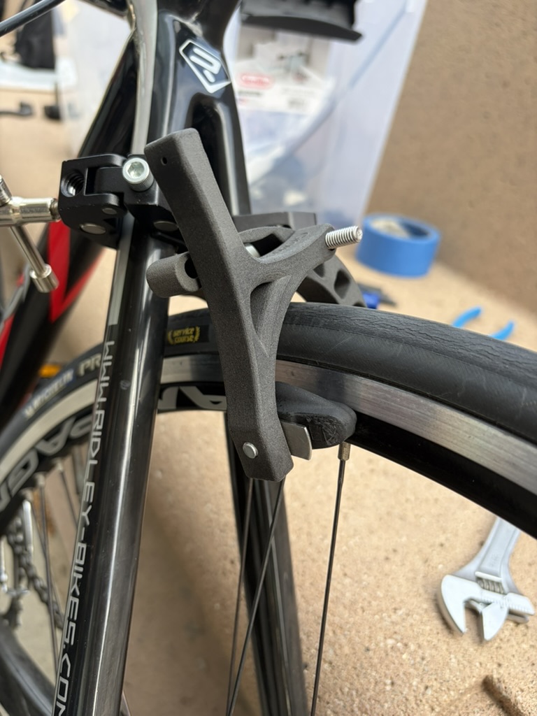
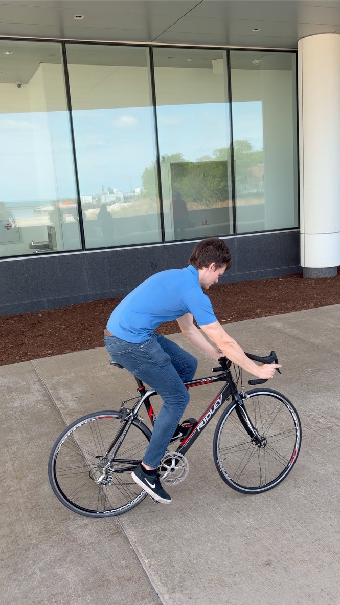
In Week 10, I helped complete the physical stopping test and compare the result against every requirement.
Outcomes
Our revised 40-gram Nylon 12 caliper stopped the bicycle in 5.334 meters, passing the 7.62-meter adjusted threshold. The final simulation reported 41.17 MPa peak stress and 7.581 mm total deflection. Compared with the first iteration, our redesign reduced the left and right peak stresses by 8.8% and 16.1% and reduced total deflection by 15.3%.
- Our redesign reduced the left and right peak stresses by 8.8% and 16.1% and reduced total deflection by 15.3%.
- Passed the braking, mass, force, stress, and deflection targets, while I identified width, released clearance, and adjustment range as the next design priorities.
I learned that FEA and topology optimization cannot rescue incorrect interfaces or missing adjustment features. The first prototype looked efficient in the model, but the installation exposed fit and usability problems that mattered more than the optimized shape. In another iteration, I would improve the overall width, released pad clearance, and adjustment range while preserving the strength and low mass we validated.