Closed-Loop DC Motor Control
Overview
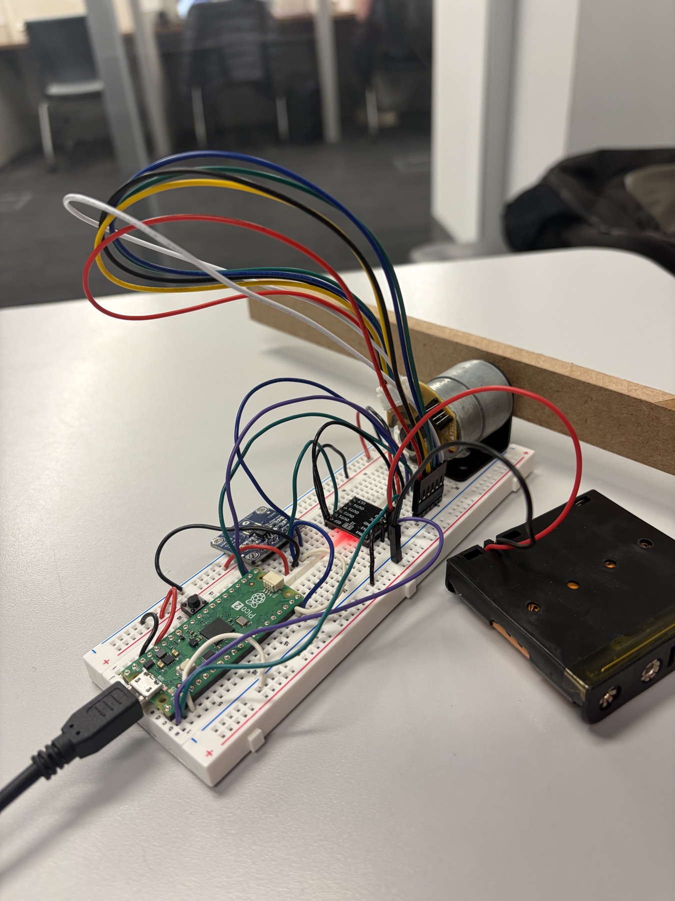
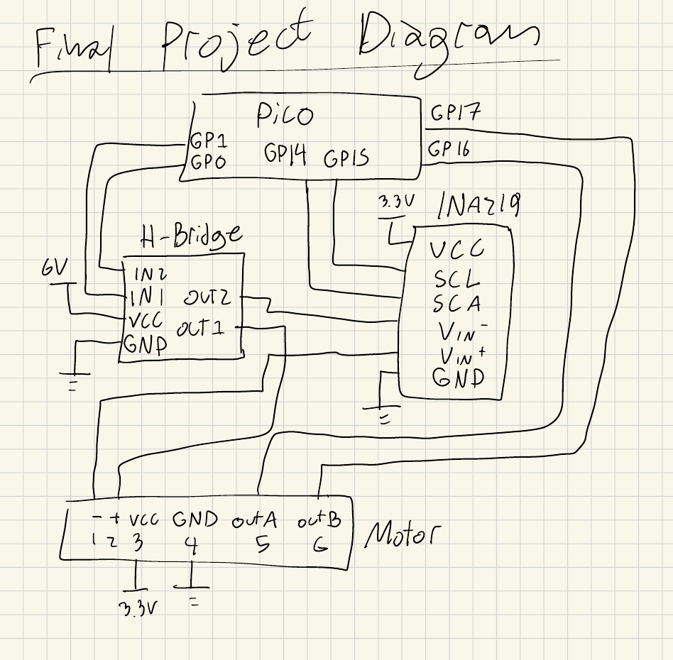
I built this system to connect power electronics, sensing, real-time firmware, and feedback control on one bench. I used an RP2040 to command a DRV8833 motor driver, read motor current through an INA219, and track shaft position with a quadrature encoder. A Python client gave me a practical way to change gains, send trajectories, and inspect measured responses without recompiling the firmware.
Skills: Embedded C · PID Control · RP2040
Goals
I set out to build a complete closed-loop motor-control system that could translate user-defined trajectories into repeatable shaft motion while keeping the electrical and mechanical dynamics independently testable.
- Run PI current control at 1 kHz.
- Run PID position control at 200 Hz.
- Track step and cubic trajectories using encoder feedback.
- Support serial tuning, testing, and data collection from a Python client.
Design
Brought up the DRV8833, INA219, and quadrature encoder independently so I could verify each hardware interface.
Implemented the PWM operating modes and closed the 1 kHz PI current loop before adding position control.
Added the 200 Hz PID position loop and generated step and cubic reference trajectories from the Python client.
Tuned the gains from the inner loop outward and compared each command against the measured current and shaft angle.
Outcomes
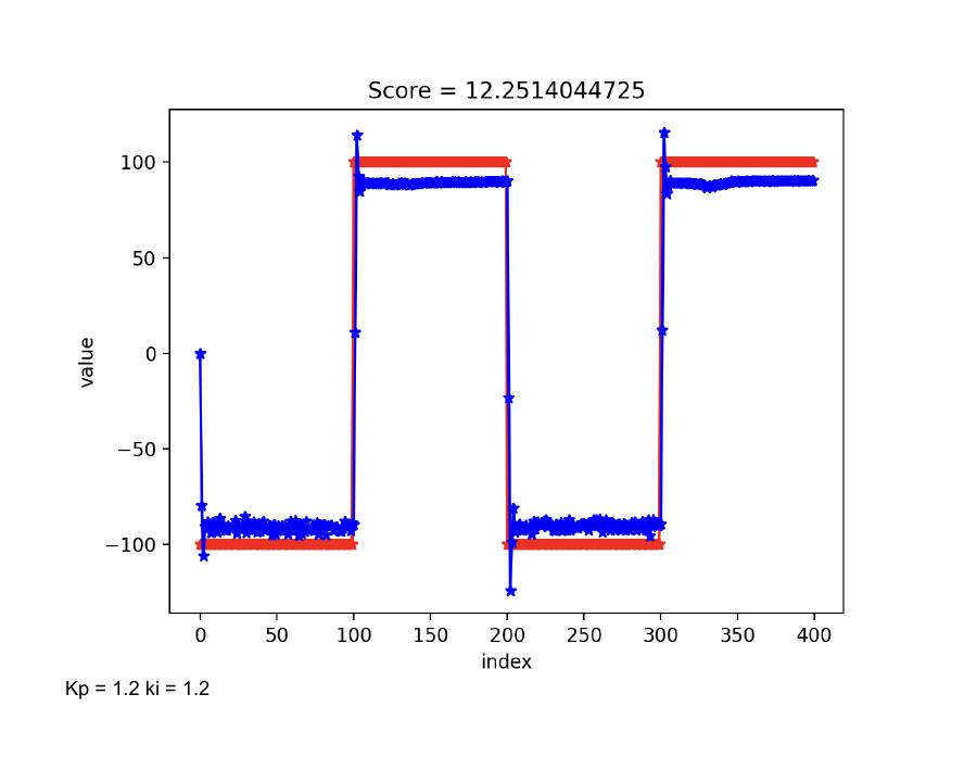
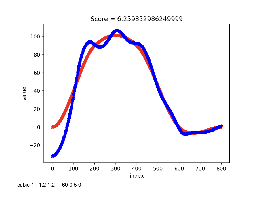
I completed a system that ran the inner current loop at 1 kHz and the outer position loop at 200 Hz, then executed both step and cubic reference trajectories. In my final documented tests, the current controller reached 12.25 mA mean absolute error during a ±100 mA square-wave test, and the best cubic trajectory reached 6.26 degrees of mean absolute position error.
- Measured 12.25 mA mean absolute error from the tuned current loop during a ±100 mA square-wave test.
- Best documented cubic trajectory achieved 6.26° mean absolute position error.
I learned to tune the system from the inner loop outward. Stabilizing and validating the current loop first made position-loop problems much easier to isolate instead of treating every error as one combined failure. In a next iteration, I would add model-based feedforward, automate repeated trajectory tests, and compare performance across a wider range of loads and speeds.